Exercises to complete:
- Connect OLED using female to female pins according to the GPIO
- Install the required software and configure OLED
- Run the stats.py script
- Enable and disable OLED via Bash scripts
The OLED Stats Display for the Raspberry Pi OS - Debian 11 Bullseye
I will walk you through the installation and configuration steps in this article so you can use the same 12864 I2C OLED display with Raspberry Pi OS Bullseye.
- Here is a video tutorial; continue reading for a list of written instructions.
What You Need For This Tutorial
- Raspberry Pi 4 or CM4 IO board with Compute Module 4
- Micro SD Card or eMMC or NVMe/SSD drive
- Power Supply aprropriate for a Raspberry Pi or CM4 IO board.
- I2C 128×64 OLED Display
- 4 female to female jumper cables
Using Your Raspberry Pi To Connect Your OLED Stats Display
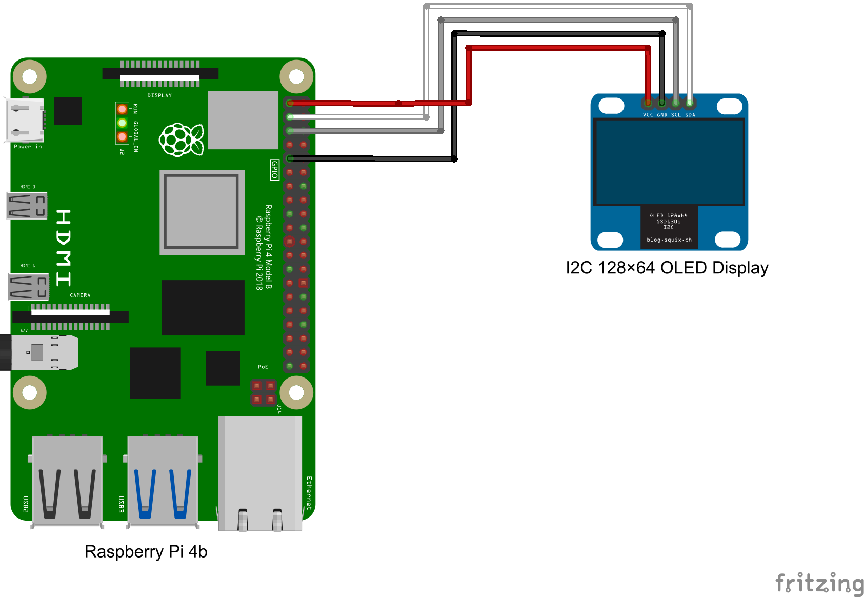
We’ll start by using the same procedure to attach the OLED stats display to our Raspberry Pi. A 4 wire female to female jumper cable is required for this. The colors are merely there to make it easier for you to remember which wire connects to which terminal and have no other use.
Since the pins protrude out the back of the OLED panel, the terminals are labeled on the front, which seems to perplex a lot of folks. This is particularly challenging to see when the display has been put into the case and the front portion of the display is hidden. Therefore, be sure to write them down before putting the display inside a case or holder.
The most typical pin configuration is GND, VCC, SCL, and SDA. Check your personal show before simply copying this configuration because some of these displays have the VCC and GND pins reversed. Even if the wiring is later corrected, if electricity is connected to them incorrectly they will likely be destroyed and cease to function.
Take note of which color is connected to which connector after plugging your ribbon cable into these four pins. It’s a good idea to note down which color is attached to which pin when fitting the monitor into your case before attaching it to your Raspberry Pi so that you don’t forget.
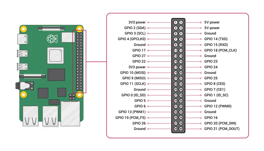
The Raspberry Pi’s GPIO pins will then accept the jumpers’ opposite ends. The GPIO pinout diagram for the Pi is readily available online and on the company’s website.

Before connecting or disconnecting jumpers from the GPIO pins, make sure your Pi is turned off and the power is off. You don’t want to forget to check your connections before turning it on and accidentally short a connection or plug a lead into the wrong pin.
For the GND and VCC jumpers, you have a few choices. I typically connect the GND jumper to Pin 9 (but you can use any pin with the designation GND). I then connect the VCC jumper to Pin 1, a 3.3V power pin. Any power pin on the GPIO header of the Raspberry Pi will function with these displays because they can run on 3.3V or 5V inputs.
The communication jumpers SCL and SDA, which are simply inserted into the respective GPIO pins, must then be connected next. Connect SDA to Pin 3 and SCL to Pin 5. Avoid confusion by ignoring the GPIO numbers on the diagram and relying solely on the SDA and SCL labels and their corresponding pin numbers.
Once you have double-checked all of your connections, you are prepared to turn on your Pi and begin configuring the display.

Programming The OLED Stats Display
After connecting the display, we may consider programming the Raspberry Pi to show the performance metrics. I’ll be doing this on a brand-new installation of Raspberry Pi OS Bullseye by flashing the operating system image to a brand-new microSD card using the Raspberry Pi Imager tool.
After inserting the SD card into the Pi’s SD card slot, connect the power supply. You ought to be on the Raspberry Pi OS desktop after starting your Pi. The same procedures can be used to install this software on a headless Pi as well.
Install the CircuitPython library and update your Raspberry Pi
Start by opening a new terminal window and running the following commands to confirm that your Pi’s software is current on all fronts:
| |
The Adafruit CircuitPython library will then be installed using the following commands:
| |
If any prompts appear, select yes (Y) and then click reboot at the conclusion.
Make sure your display is visible.
I2C connectivity, which is required to communicate with the display, should have been activated by the prior installation script as well. By executing the following command, you can verify that it is enabled and your Pi can view the attached display:
| |
Then, a table with a single set of characters (usually 3c for these displays) should appear, similar to the one below. Your display’s I2C address is indicated by this code.
If it hasn’t appeared, either your wiring is incorrect or I2C communication isn’t enabled, which may be done using the setup utility. You’ve likely made a wiring error if you see a table filled with characters (all addresses are displayed), as this occurs when SDA is shorted to ground. After a reboot, go back and double-check your connections to the Pi and the display, as well as whether I2C communication is enabled.
Use the configuration utility and type the following to enable I2C communication:
| |
If you don’t obtain the right response at this phase, stop trying to make the script work. Your Raspberry Pi won’t be able to communicate with the connected display to get anything displayed if it can’t see it.
Install The OLED Stats Display Script
The CircuitPython libraries related to the display must then be installed. Enter the following commands to get started:
| |
All that’s left to do is download the script itself. You only need to execute the following line to copy it to your Pi because I made it accessible on Github in its finished form rather than attempting to edit it on the Raspberry Pi:
| |
Now type the below command to enter the directory you already cloned:
| |
Run the script after that by typing:
| |
Making The Script Run Automatically On Startup
Now that the display is running, we would like it to do so automatically when the computer starts up because it will cease as soon as we close the terminal window. We’re going to use crontab to accomplish this.
Enter the next command to launch crontab:
| |
If you’re opening crontab for the first time, you’ll be asked to choose an editor; choose 1 and press enter.
To execute the script, include the following line at the end of the file:
| |
Remember to add the “&” at the end to instruct the Pi to continue booting up and to continue running the script.
The stats.py script and font also need to be copied into the home directory. The right path in the prior step can also be directly referenced, but I find this to be less dependable.
Make care to copy the PixelOperator typeface and the stats.py script to the /home/username directory.
| |
You must change the crontab command such that it reads: If you decide to leave them in the downloaded directory.
| |
When you finish, save the crontab file, and then reboot your Pi to check if everything is operating as it should.
If you followed the steps exactly, you should now have a functional OLED statistics display that launches whenever your Raspberry Pi boots up. If you haven’t already, you can go ahead and put it into your case immediately.
How to enable and disable OLED
Create two bash scripts in OLED_Stats directory:
| |
Now edit the killer script:
| |
And put the below content into it:
| |
Then edit the enabler script:
| |
And put the below content into it:
| |
Now copy the stats.py to a new file
| |
Edit the stats-off.py script
| |
And change the below section:
| |
into this:
| |
Save and exit.
Please share your thoughts on this tutorial in the space provided below. Please share your thoughts and recommendations with me.
Comments